
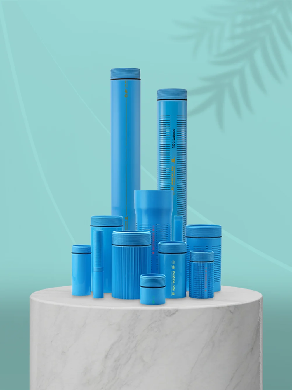
uPVC Casing Pipes for Borewell & Tubewell
Designed for borewell contractors, farmers, project engineers and dealers working on borewell and tubewell projects across India.
Duke uPVC casing pipes are designed to provide a stable casing system for borewell and tubewell applications. The current technical range includes multiple casing and screen configurations with detailed specifications for nominal diameter, actual outside diameter, wall thickness, connection diameter, thread length and screen parameters.
The correct casing pipe should be selected according to the bore design, actual pipe dimensions, geological conditions and screen requirement—not by nominal inch size or price alone.
Relevant Indian Standard: IS 12818:2010 covers PVC-U screen and casing pipes for bore/tubewells.
Manufacturer: Duke Pipes Private Limited, Gujarat, India
Manufacturing piping solutions since: 1998
CTA: View Technical Specifications
CTA: Request Current Price
What Is a uPVC Casing Pipe?
A uPVC casing pipe is installed inside a drilled borewell or tubewell to provide a stable lining for the bore. Plain casing is generally used where structural support is required, while screen sections allow groundwater to enter through designed openings in selected water-bearing zones.
uPVC is commonly used for borewell casing because it does not suffer from conventional metal rusting, is comparatively lightweight and can be manufactured in different sizes and casing or screen configurations.
The relevant Indian Standard for this product category is IS 12818:2010 — Unplasticized Polyvinyl Chloride (PVC-U) Screen and Casing Pipes for Bore/Tubewells.
Why Choose Duke uPVC Casing Pipes?
Duke Pipes manufactures uPVC casing solutions with detailed technical dimensions to help contractors, project buyers and dealers select pipes according to actual borewell requirements.
Corrosion-Resistant uPVC
uPVC does not rust like conventional ferrous metal casing, making it suitable for many underground water applications.
Lightweight Handling
Its comparatively low weight helps simplify transportation, site handling and pipe lowering.
Threaded Connections
Duke casing pipes use threaded connection arrangements for joining individual pipe sections during installation.
Multiple Casing Configurations
The Duke technical range includes CS, CM and CD casing pipes along with additional configurations shown in the Technical Parameters section.
Casing and Screen Options
Plain casing and screen pipe options allow different sections of a borewell to perform different functions.
Detailed Dimensional Data
Duke publishes nominal diameter, mean outside diameter, wall thickness, maximum connection diameter and thread-length data so selection can be based on actual measurements rather than only nominal size.
For the water-lifting section of a borewell system, explore uPVC column pipes for submersible pumps.
Which Duke Casing Pipe Series Should You Choose?
Duke’s technical range includes CS, CM and CD casing pipes for different borewell requirements.
The correct series should not be selected only by price.
Before choosing a casing series, consider:
- Bore depth
- Drilled bore diameter
- Geological or soil conditions
- Required nominal casing diameter
- Actual outside diameter
- Maximum diameter over the connection
- Required wall thickness
- Plain or screen requirement
- Installation conditions
Exact depth suitability should always be checked against Duke’s latest approved technical specifications before installation.
If you are still deciding which type is suitable for your project, read our guide on how to choose the best casing pipe for a borewell.
What uPVC Casing Pipe Sizes Are Available?
Across Duke’s currently published technical tables, casing sizes vary by series and extend from smaller nominal diameters through DN400, depending on the configuration.
For example:
- CS casing tables currently include DN100 through DN400.
- CM casing tables currently include DN35 through DN400.
- CD casing tables currently include DN100 through DN400.
Additional R-CS, R-CM and R-CD technical tables are also available on the page.
Before ordering, always check:
- Nominal diameter in millimetres
- Nominal inch reference
- Minimum and maximum mean outside diameter
- Minimum and maximum wall thickness
- Maximum outer diameter over the connection
- Thread length
Nominal Size Is Not the Same as Actual Outside Diameter
This distinction is important when matching a casing pipe to a drilled bore.
A pipe commonly described as a 6-inch casing pipe is not necessarily exactly 6 inches across its outside surface.
Example: Duke’s current CS technical table lists DN150, commonly referenced as 6 inch, with a mean outside diameter of approximately 165.0–165.4 mm. Its maximum outside diameter over the connection is 174 mm.
This is why casing clearance should be calculated using the actual pipe and connection dimensions rather than the nominal inch description alone.
For a broader understanding of casing, column and other borewell components, read the complete borewell pipe guide.
Duke uPVC Casing Pipe Technical Specifications
The Technical Parameters section should remain a key part of this product page.
CS Casing Pipe
CM Casing Pipe
CD Casing Pipe
R-CS Casing Pipe
R-CM Casing Pipe
R-CD Casing Pipe
RMS/PMS Screen Open Area
RDS/PDS Screen Open Area
Screen Permeability
Slot Width Tolerance
Do not convert these specification tables into images.
For clearer reading and better search-engine interpretation, use these column names consistently:
Nominal Diameter
Mean Outside Diameter (mm)
Wall Thickness (mm)
Maximum Outside Diameter Over Connection (mm)
Thread Length (mm)
Use Minimum and Maximum instead of only “min” and “max” where layout permits.
For the R-CS table, remove quotation marks from values in the millimetre column. For example, display 100 under mm and 4.0″ under inch—not 100" under mm.
Technical buyers can also download Duke Pipes technical specifications and brochures.
What Are the Dimensions of a 6.5-Inch Duke Casing Pipe?
Duke’s current technical tables include DN165 / 6.5-inch nominal casing in CS, CM and CD configurations.
The actual dimensions vary according to series.
| Series | Nominal Size | Mean Outside Diameter | Wall Thickness | Maximum Connection OD |
|---|---|---|---|---|
| CS | DN165 / 6.5″ | 180.0–180.3 mm | 6.10–7.10 mm | 188 mm |
| CM | DN165 / 6.5″ | 180.0–180.4 mm | 8.0–8.5 mm | 196.7 mm |
| CD | DN165 / 6.5″ | 180.0–180.4 mm | 12.0–12.5 mm | 200 mm |
This comparison shows why a buyer requesting a 6.5-inch casing pipe price should also specify the required series. The nominal diameter may be the same while wall thickness and connection dimensions differ.
Plain Casing Pipe vs Screen Pipe
Plain casing and screen pipes perform different functions inside a borewell.
| Pipe Type | Main Purpose |
| Plain Casing Pipe | Provides a solid casing section where water entry through the pipe wall is not required |
| Screen Pipe | Uses designed slots/openings to allow groundwater entry in selected borewell sections |
Duke’s technical section includes screen data covering factors such as nominal diameter, number of slots, slot width, open passage area and permeability.
The screen configuration should be selected according to borewell design and geological conditions rather than simply using the same screen at every depth.
How Should You Read the Screen Pipe Technical Tables?
Duke’s screen tables provide more than a simple pipe diameter.
Depending on the screen configuration, technical data includes:
- Nominal diameter
- Minimum number of slots
- Slot width
- Free passage/open area percentage
- Permeability data
- Slot-width tolerance
These values help engineers and borewell professionals compare screen configurations for different project requirements.
Any technical symbol or abbreviation used in the table, including values such as Σa ±5%, should have a short legend or definition beside the table based on Duke’s approved technical documentation.
Where Are Duke uPVC Casing Pipes Used?
Duke uPVC casing pipes are designed for suitable borewell and tubewell applications where a stable casing or screen system is required.
Typical use cases include:
- Borewell and tubewell casing
- Agricultural groundwater projects
- Farm and irrigation water-source installations
- Domestic borewell systems
- Industrial groundwater installations
- Projects requiring a combination of plain casing and screen sections
The final casing configuration should be selected according to the site’s bore design and installation requirements.
How Do You Select the Right uPVC Casing Pipe?
The right casing pipe is the one that matches the technical requirements of the borewell—not simply the lowest-priced or largest available pipe.
Before requesting a quotation, confirm:
- Bore depth
- Drilled bore diameter
- Required nominal casing size
- Actual outside diameter
- Maximum connection diameter
- Ground or geological conditions
- Plain or screen requirement
- Required casing series
- Quantity
- Delivery location
If you do not yet know the exact series, provide the project details to the Duke Pipes team so the relevant technical specifications can be reviewed.
What Determines uPVC Casing Pipe Price?
There is no single fixed uPVC casing pipe price for every borewell project.
Price can vary according to:
- Nominal diameter
- Casing series
- Wall thickness
- Plain or screen configuration
- Required pipe length
- Quantity
- Delivery location
- Transportation
- Current commercial pricing
Two pipes described using the same nominal inch size may therefore have different specifications and prices.
Looking for Duke Casing Pipe Pricing by Size or Length?
If you are searching for a 6.5-inch casing pipe price, Duke casing pipe price, or pricing for a particular pipe length, share:
- Required nominal diameter
- Required series, if known
- Plain or screen requirement
- Quantity
- Bore depth, if available
- Delivery city and state
Duke Pipes can then confirm current product availability and provide a more relevant quotation.
Request current uPVC casing pipe pricing.
Installation & Jointing Guidance
uPVC casing installation should be carried out by experienced borewell professionals and according to the latest product instructions.
Before and during installation:
- Confirm actual pipe and connection dimensions
- Inspect pipes and threads for transport damage
- Keep threaded surfaces clean
- Maintain proper alignment while joining
- Avoid cross-threading or forcing connections
- Check bore clearance before lowering the casing
- Use plain and screen sections according to the well design
- Review the installation if actual geological conditions differ from the original plan
Project-specific installation decisions should always follow the applicable technical specification and site conditions.
Why Choose Duke as a uPVC Casing Pipe Manufacturer?
Duke Pipes Private Limited has been manufacturing piping solutions in Gujarat, India since 1998.
For contractors, dealers and project buyers comparing a uPVC casing pipe manufacturer, useful factors include more than promotional claims.
Duke provides:
- Detailed dimensional tables
- Multiple casing configurations
- Plain and screen pipe technical data
- Outside diameter and wall-thickness information
- Connection and thread dimensions
- Product brochures and technical resources
- Product-selection and quotation support
This technical information allows buyers to compare products using actual project requirements before ordering.
Request the Right uPVC Casing Pipe for Your Project
For current availability, technical guidance or project-specific pricing, keep these details ready:
- Bore depth
- Drilled bore diameter
- Required nominal casing size
- Plain or screen requirement
- Series, if known
- Quantity
- Delivery city/state
Contact Duke Pipes for current casing pipe pricing and product guidance.
Phone: +91 73920 73920
Email: [email protected]
For complete borewell selection guidance, read Best uPVC Casing Pipe for Borewell in India.
Select the correct specification first. Compare the price second.
CS Casing Pipe
| Nominal Diameter | Mean Outer Diameter (mm) | Wall Thickness | Mean Outer Dia Over Connection (Max) | Length of Threads | |||
|---|---|---|---|---|---|---|---|
| mm | inch | min | max | min | max | ||
| 100 | 4.0 | 113.0 | 113.3 | 4.60 | 5.20 | 116.0 | 48 |
| 125 | 5.0 | 140.0 | 140.4 | 5.30 | 5.60 | 148.0 | 63 |
| 150 | 6.0 | 165.0 | 165.4 | 5.70 | 6.50 | 174.0 | 63 |
| 165 | 6.5 | 180.0 | 180.3 | 6.10 | 7.10 | 188.0 | 63 |
| 175 | 7.0 | 200.0 | 200.5 | 7.00 | 7.80 | 211.0 | 63 |
| 200 | 8.0 | 225.0 | 225.5 | 7.60 | 8.80 | 238.0 | 74 |
| 225 | 9.0 | 250.0 | 250.5 | 8.80 | 9.60 | 262.0 | 74 |
| 250 | 10.0 | 280.0 | 280.5 | 9.60 | 11.0 | 292.0 | 90 |
| 300 | 12.0 | 330.0 | 330.6 | 11.2 | 13.3 | 346.0 | 90 |
| 350 | 14.0 | 400.0 | 400.7 | 14.0 | 15.5 | 420.0 | 90 |
| 400 | 16.0 | 450.0 | 450.8 | 16.0 | 17.5 | 470.0 | 102 |
CM Casing Pipe
| Nominal Diameter | Mean Outer Diameter (mm) | Wall Thickness | Mean Outer Dia Over Connection (Max) | Length of Threads | |||
|---|---|---|---|---|---|---|---|
| mm | inch | min | max | min | max | ||
| 35 | 1.25″ | 42.0 | 42.2 | 3.5 | 4.0 | 46.0 | 25 |
| 40 | 1.5″ | 48.0 | 48.2 | 3.5 | 4.0 | 52.0 | 25 |
| 50 | 2.0″ | 60.0 | 60.2 | 4.0 | 4.6 | 65.0 | 30 |
| 80 | 3.0″ | 88.0 | 88.3 | 4.0 | 4.6 | 94.0 | 40 |
| 100 | 4.0″ | 113.0 | 113.3 | 5.0 | 5.7 | 120.0 | 48 |
| 115 | 4.5″ | 125.0 | 125.3 | 5.0 | 5.7 | 132.0 | 48 |
| 125 | 5.0″ | 140.0 | 140.4 | 6.5 | 7.3 | 150.0 | 63 |
| 150 | 6.0″ | 165.0 | 165.4 | 7.5 | 8.5 | 178.0 | 63 |
| 165* | 6.5″ | 180.0 | 180.4 | 8.0 | 8.5 | 196.7 | 63 |
| 175 | 7.0″ | 200.0 | 200.5 | 8.8 | 9.8 | 215.0 | 63 |
| 200 | 8.0″ | 225.0 | 225.5 | 10.0 | 11.2 | 243.0 | 74 |
| 225* | 9.0″ | 250.0 | 250.5 | 12.0 | 12.5 | 270.0 | 74 |
| 250 | 10.0″ | 280.0 | 280.5 | 12.5 | 14.0 | 298.0 | 90 |
| 300 | 12.0″ | 330.0 | 330.6 | 14.5 | 16.2 | 352.0 | 90 |
| 350 | 14.0″ | 400.0 | 400.7 | 17.5 | 19.5 | 428.0 | 90 |
| 400 | 16.0″ | 450.0 | 450.8 | 19.5 | 21.7 | 479.0 | 102 |
CD Casing Pipe
| Nominal Diameter | Mean Outer Diameter (mm) | Wall Thickness | Mean Outer Dia Over Connection (Max) | Length of Threads | |||
|---|---|---|---|---|---|---|---|
| mm | inch | min | max | min | max | ||
| 100 | 4.0″ | 113.0 | 113.3 | 7.00 | 7.90 | 125.0 | 48 |
| 115 | 4.5″ | 125.0 | 125.3 | 7.50 | 8.50 | 137.0 | 48 |
| 125 | 5.0″ | 140.0 | 140.4 | 8.00 | 9.00 | 152.0 | 63 |
| 150 | 6.0″ | 165.0 | 165.4 | 9.50 | 10.70 | 180.0 | 63 |
| 165* | 6.5″ | 180.0 | 180.4 | 12.00 | 12.50 | 200.0 | 63 |
| 175 | 7.0″ | 200.0 | 200.5 | 11.80 | 13.60 | 217.0 | 63 |
| 200 | 8.0″ | 225.0 | 225.5 | 13.00 | 14.80 | 247.0 | 74 |
| 225* | 9.0″ | 250.0 | 250.5 | 14.50 | 15.50 | 270.0 | 74 |
| 250 | 10.0″ | 280.0 | 280.5 | 16.00 | 17.6 | 304.0 | 90 |
| 300 | 12.0″ | 330.0 | 330.6 | 19.0 | 21.0 | 359.0 | 90 |
| 350 | 14.0″ | 400.0 | 400.7 | 21.5 | 23.9 | 433.0 | 90 |
| 400 | 16.0″ | 450.0 | 450.8 | 23.5 | 26.1 | 490.0 | 102 |
R – CS Casing Pipe
| Nominal Diameter | Mean Outer Diameter (mm) | Wall Thickness | Mean Outer Dia Over Connection (Max) | Length of Threads | |||
|---|---|---|---|---|---|---|---|
| mm | inch | min | max | min | max | ||
| 100″ | 4.0 | 117.0 | 117.3 | 4.60 | 5.20 | 120.0 | 48 |
| 125″ | 5.0 | 144.0 | 144.4 | 5.30 | 5.60 | 152.0 | 63 |
| 150″ | 6.0 | 169.0 | 169.4 | 5.70 | 6.50 | 178.0 | 63 |
| 175″ | 7.0 | 204.0 | 204.5 | 7.00 | 7.80 | 215.0 | 63 |
| 200″ | 8.0 | 229.0 | 229.5 | 7.60 | 8.80 | 242.0 | 74 |
| 250″ | 10.0 | 284.0 | 284.5 | 9.60 | 11.0 | 296.0 | 90 |
| 300″ | 12.0 | 334.0 | 334.6 | 11.20 | 13.30 | 350.0 | 90 |
R – CM Casing Pipe
| Nominal Diameter | Mean Outer Diameter (mm) | Wall Thickness | Mean Outer Dia Over Connection (Max) | Length of Threads | |||
|---|---|---|---|---|---|---|---|
| mm | inch | min | max | min | max | ||
| 35 | 1.25″ | 46.0 | 46.2 | 3.5 | 4.0 | 50.0 | 25 |
| 40 | 1.5″ | 52.0 | 52.2 | 3.5 | 4.0 | 56.0 | 25 |
| 50 | 2.0″ | 64.0 | 64.2 | 4.0 | 4.6 | 69.0 | 30 |
| 80 | 3.0″ | 92.0 | 92.3 | 4.0 | 4.6 | 98.0 | 40 |
| 100 | 4.0″ | 117.0 | 117.3 | 5.0 | 5.7 | 124.0 | 48 |
| 125 | 5.0″ | 144.0 | 144.4 | 6.5 | 7.3 | 154.0 | 63 |
| 150 | 6.0″ | 169.0 | 169.4 | 7.5 | 8.5 | 182.0 | 63 |
| 175 | 7.0″ | 204.0 | 204.5 | 8.8 | 9.8 | 219.0 | 63 |
| 200 | 8.0″ | 229.0 | 229.5 | 10.0 | 11.2 | 247.0 | 74 |
| 250 | 10.0″ | 284.0 | 284.5 | 12.5 | 14.0 | 302.0 | 90 |
| 300 | 12.0″ | 334.0 | 334.6 | 14.5 | 16.2 | 356.0 | 90 |
| 350 | 14.0″ | 404.0 | 404.7 | 17.5 | 19.5 | 432.0 | 90 |
| 400 | 16.0″ | 454.0 | 454.8 | 19.5 | 21.7 | 483.0 | 102 |
R – CD Casing Pipe
| Nominal Diameter | Mean Outer Diameter (mm) | Wall Thickness | Mean Outer Dia Over Connection (Max) | Length of Threads | |||
|---|---|---|---|---|---|---|---|
| mm | inch | min | max | min | max | ||
| 100 | 4.0″ | 117.0 | 117.3 | 7.0 | 7.9 | 129.0 | 48 |
| 115 | 4.5″ | 129.0 | 129.3 | 7.5 | 8.5 | 141.0 | 48 |
| 125 | 5.0″ | 144.0 | 144.4 | 8.0 | 9.0 | 156.0 | 63 |
| 150 | 6.0″ | 169.0 | 169.4 | 9.5 | 10.7 | 184.0 | 63 |
| 175 | 7.0″ | 204.0 | 204.5 | 11.8 | 13.6 | 221.0 | 63 |
| 200 | 8.0″ | 229.0 | 229.5 | 13.0 | 14.8 | 251.0 | 74 |
| 250 | 10.0″ | 284.0 | 284.5 | 16.0 | 17.6 | 309.0 | 90 |
| 300 | 12.0″ | 334.0 | 334.6 | 19.0 | 21.0 | 363.0 | 90 |
| 350 | 14.0″ | 404.0 | 404.7 | 21.5 | 23.9 | 437.0 | 90 |
| 400 | 16.0″ | 454.0 | 454.8 | 23.5 | 26.1 | 494.0 | 102 |
Screen Open Area in Percent for width of slot (w)
| RMS/PMS | |||||||||||
|---|---|---|---|---|---|---|---|---|---|---|---|
| Nominal Diameter | Number of Slot N (Min) | Σα ± 5% | Slot width in mm | ||||||||
| Free passage area in Percentage | |||||||||||
| mm | inch | 0.2 | 0.3 | 0.5 | 0.75 | 1.0 | 1.5 | 2.0 | 3.0 | ||
| 35 | 1.25 | 3 | 75 | 3.7 | 5.2 | 6.0 | 9.1 | 9.4 | 9.7 | 12.1 | — |
| 40 | 1.5 | 3 | 85 | 3.7 | 5.2 | 6.0 | 9.1 | 9.4 | 9.7 | 12.1 | — |
| 50 | 2 | 3 | 108 | 3.7 | 5.2 | 6.0 | 9.1 | 9.4 | 9.7 | 12.1 | — |
| 80 | 3 | 3 | 168 | 3.7 | 5.2 | 6.0 | 9.1 | 9.4 | 9.7 | 12.1 | — |
| 100 | 4 | 5 | 216 | 3.7 | 5.2 | 6.0 | 9.1 | 9.4 | 9.7 | 12.1 | 14.0 |
| 115 | 4.5 | 5 | 240 | 3.7 | 5.2 | 6.0 | 9.1 | 9.4 | 9.7 | 12.1 | 14.0 |
| 125 | 5 | 5 | 240 | — | 4.7 | 5.6 | 8.2 | 8.5 | 8.8 | 11.0 | 13.5 |
| 150 | 6 | 5 | 285 | — | — | 5.6 | 8.2 | 8.5 | 8.8 | 11.0 | 13.5 |
| 175 | 7 | 6 | 340 | — | — | 5.6 | 8.3 | 8.5 | 8.8 | 11.0 | 13.5 |
| 200 | 8 | 6 | 390 | — | — | — | 8.3 | 8.5 | 8.8 | 11.0 | 13.5 |
| 250 | 10 | 6 | 450 | — | — | — | 7.6 | 7.9 | 8.1 | 10.2 | 12.5 |
| 300 | 12 | 6 | 530 | — | — | — | 7.6 | 7.9 | 8.1 | 10.2 | 12.5 |
| 350 | 14 | 8 | 640 | — | — | — | — | 7.9 | 8.1 | 10.2 | 12.5 |
| 400 | 16 | 8 | 720 | — | — | — | — | 7.9 | 8.1 | 10.2 | 12.5 |
| Slot pitch mm b±0.5 mm | 4.0 | 4.0 | 5.5 | 5.5 | 6.8 | 9.5 | 9.5 | 11.0 | |||
| RDS/PDS | |||||||||||
|---|---|---|---|---|---|---|---|---|---|---|---|
| Nominal Diameter | Number of Slot N (Min) | Σα ± 5% | Slot width in mm | ||||||||
| Free passage area in Percentage | |||||||||||
| mm | inch | 0.2 | 0.3 | 0.5 | 0.75 | 1.0 | 1.5 | 2.0 | 3.0 | ||
| 100 | 4 | 5 | 206 | — | 5.2 | 6.0 | 9.1 | 9.4 | 9.7 | 12.1 | — |
| 115 | 4.5 | 5 | 230 | — | 5.2 | 6.0 | 9.1 | 9.4 | 9.7 | 12.1 | — |
| 125 | 5 | 5 | 235 | — | — | 5.6 | 8.2 | 8.5 | 8.8 | 11.0 | 13.5 |
| 150 | 6 | 5 | 278 | — | — | 5.6 | 8.2 | 8.5 | 8.8 | 11.0 | 13.5 |
| 175 | 7 | 6 | 330 | — | — | — | 8.3 | 8.5 | 8.8 | 11.0 | 13.5 |
| 200 | 8 | 6 | 380 | — | — | — | 7.6 | 7.9 | 8.1 | 10.2 | 12.5 |
| 250 | 10 | 6 | 435 | — | — | — | 7.6 | 7.9 | 8.1 | 10.2 | 12.5 |
| 300 | 12 | 6 | 512 | — | — | — | 7.6 | 7.9 | 8.1 | 10.2 | 12.5 |
| 350 | 14 | 8 | 626 | — | — | — | — | 7.9 | 8.1 | 10.2 | 12.5 |
| 400 | 16 | 8 | 706 | — | — | — | — | 7.9 | 8.1 | 10.2 | 12.5 |
| Slot pitch mm b±0.5 mm | 4.0 | 4.0 | 5.5 | 5.5 | 6.8 | 9.5 | 9.5 | 11.0 | |||
Screen Permeability for width of slot
| RMS/PMS | |||||||||||
|---|---|---|---|---|---|---|---|---|---|---|---|
| Nominal Diameter | Slot width in mm | ||||||||||
| Free passage area in Percentage | |||||||||||
| mm | inch | 0.2 | 0.3 | 0.5 | 0.75 | 1.0 | 1.5 | 2.0 | 3.0 | ||
| 50 | 2.0 | 0.18 | 0.25 | 0.29 | 0.44 | 0.45 | 0.46 | 0.58 | 0.67 | ||
| 80 | 3.0 | 0.27 | 0.39 | 0.45 | 0.68 | 0.70 | 0.72 | 0.90 | 1.04 | ||
| 100 | 4.0 | 0.35 | 0.50 | 0.57 | 0.87 | 0.90 | 0.93 | 1.16 | 1.34 | ||
| 115 | 4.5 | 0.40 | 0.56 | 0.64 | 0.97 | 1.01 | 1.04 | 1.30 | 1.50 | ||
| 125 | 5.0 | — | 0.56 | 0.66 | 0.97 | 1.00 | 1.04 | 1.30 | 1.59 | ||
| 150 | 6.0 | — | — | 0.78 | 1.15 | 1.19 | 1.23 | 1.54 | 1.89 | ||
| 175 | 7.0 | — | — | 0.93 | 1.38 | 1.41 | 1.46 | 1.82 | 2.24 | ||
| 200 | 8.0 | — | — | — | 1.59 | 1.62 | 1.68 | 2.10 | 2.58 | ||
| 250 | 10.0 | — | — | — | 1.81 | 1.88 | 1.93 | 2.42 | 2.97 | ||
| 300 | 12.0 | — | — | — | 2.13 | 2.22 | 2.27 | 2.86 | 3.51 | ||
Tolerance On Width of slot (w)
| Slot width (W) mm | 0.2 | 0.3 | 0.5 | 0.75 | 1.0 | 1.5 | 2.0 | 3.0 |
|---|---|---|---|---|---|---|---|---|
| Tolerance (mm) | +0.06 | +0.06 | +0.10 | +0.20 | +0.20 | +0.20 | +0.20 | +0.30 |
| -0.00 | -0.00 | -0.00 | -0.00 | -0.00 | -0.00 | -0.00 | -0.00 |
uPVC Casing Pipes for Borewell & Tubewell
Designed for borewell contractors, farmers, project engineers and dealers working on borewell and tubewell projects across India.
Duke uPVC casing pipes are designed to provide a stable casing system for borewell and tubewell applications. The current technical range includes multiple casing and screen configurations with detailed specifications for nominal diameter, actual outside diameter, wall thickness, connection diameter, thread length and screen parameters.
The correct casing pipe should be selected according to the bore design, actual pipe dimensions, geological conditions and screen requirement—not by nominal inch size or price alone.
Relevant Indian Standard: IS 12818:2010 covers PVC-U screen and casing pipes for bore/tubewells.
Manufacturer: Duke Pipes Private Limited, Gujarat, India
Manufacturing piping solutions since: 1998
CTA: View Technical Specifications
CTA: Request Current Price
What Is a uPVC Casing Pipe?
A uPVC casing pipe is installed inside a drilled borewell or tubewell to provide a stable lining for the bore. Plain casing is generally used where structural support is required, while screen sections allow groundwater to enter through designed openings in selected water-bearing zones.
uPVC is commonly used for borewell casing because it does not suffer from conventional metal rusting, is comparatively lightweight and can be manufactured in different sizes and casing or screen configurations.
The relevant Indian Standard for this product category is IS 12818:2010 — Unplasticized Polyvinyl Chloride (PVC-U) Screen and Casing Pipes for Bore/Tubewells.
Why Choose Duke uPVC Casing Pipes?
Duke Pipes manufactures uPVC casing solutions with detailed technical dimensions to help contractors, project buyers and dealers select pipes according to actual borewell requirements.
Corrosion-Resistant uPVC
uPVC does not rust like conventional ferrous metal casing, making it suitable for many underground water applications.
Lightweight Handling
Its comparatively low weight helps simplify transportation, site handling and pipe lowering.
Threaded Connections
Duke casing pipes use threaded connection arrangements for joining individual pipe sections during installation.
Multiple Casing Configurations
The Duke technical range includes CS, CM and CD casing pipes along with additional configurations shown in the Technical Parameters section.
Casing and Screen Options
Plain casing and screen pipe options allow different sections of a borewell to perform different functions.
Detailed Dimensional Data
Duke publishes nominal diameter, mean outside diameter, wall thickness, maximum connection diameter and thread-length data so selection can be based on actual measurements rather than only nominal size.
For the water-lifting section of a borewell system, explore uPVC column pipes for submersible pumps.
Which Duke Casing Pipe Series Should You Choose?
Duke’s technical range includes CS, CM and CD casing pipes for different borewell requirements.
The correct series should not be selected only by price.
Before choosing a casing series, consider:
- Bore depth
- Drilled bore diameter
- Geological or soil conditions
- Required nominal casing diameter
- Actual outside diameter
- Maximum diameter over the connection
- Required wall thickness
- Plain or screen requirement
- Installation conditions
Exact depth suitability should always be checked against Duke’s latest approved technical specifications before installation.
If you are still deciding which type is suitable for your project, read our guide on how to choose the best casing pipe for a borewell.
What uPVC Casing Pipe Sizes Are Available?
Across Duke’s currently published technical tables, casing sizes vary by series and extend from smaller nominal diameters through DN400, depending on the configuration.
For example:
- CS casing tables currently include DN100 through DN400.
- CM casing tables currently include DN35 through DN400.
- CD casing tables currently include DN100 through DN400.
Additional R-CS, R-CM and R-CD technical tables are also available on the page.
Before ordering, always check:
- Nominal diameter in millimetres
- Nominal inch reference
- Minimum and maximum mean outside diameter
- Minimum and maximum wall thickness
- Maximum outer diameter over the connection
- Thread length
Nominal Size Is Not the Same as Actual Outside Diameter
This distinction is important when matching a casing pipe to a drilled bore.
A pipe commonly described as a 6-inch casing pipe is not necessarily exactly 6 inches across its outside surface.
Example: Duke’s current CS technical table lists DN150, commonly referenced as 6 inch, with a mean outside diameter of approximately 165.0–165.4 mm. Its maximum outside diameter over the connection is 174 mm.
This is why casing clearance should be calculated using the actual pipe and connection dimensions rather than the nominal inch description alone.
For a broader understanding of casing, column and other borewell components, read the complete borewell pipe guide.
Duke uPVC Casing Pipe Technical Specifications
The Technical Parameters section should remain a key part of this product page.
CS Casing Pipe
CM Casing Pipe
CD Casing Pipe
R-CS Casing Pipe
R-CM Casing Pipe
R-CD Casing Pipe
RMS/PMS Screen Open Area
RDS/PDS Screen Open Area
Screen Permeability
Slot Width Tolerance
Do not convert these specification tables into images.
For clearer reading and better search-engine interpretation, use these column names consistently:
Nominal Diameter
Mean Outside Diameter (mm)
Wall Thickness (mm)
Maximum Outside Diameter Over Connection (mm)
Thread Length (mm)
Use Minimum and Maximum instead of only “min” and “max” where layout permits.
For the R-CS table, remove quotation marks from values in the millimetre column. For example, display 100 under mm and 4.0″ under inch—not 100" under mm.
Technical buyers can also download Duke Pipes technical specifications and brochures.
What Are the Dimensions of a 6.5-Inch Duke Casing Pipe?
Duke’s current technical tables include DN165 / 6.5-inch nominal casing in CS, CM and CD configurations.
The actual dimensions vary according to series.
| Series | Nominal Size | Mean Outside Diameter | Wall Thickness | Maximum Connection OD |
|---|---|---|---|---|
| CS | DN165 / 6.5″ | 180.0–180.3 mm | 6.10–7.10 mm | 188 mm |
| CM | DN165 / 6.5″ | 180.0–180.4 mm | 8.0–8.5 mm | 196.7 mm |
| CD | DN165 / 6.5″ | 180.0–180.4 mm | 12.0–12.5 mm | 200 mm |
This comparison shows why a buyer requesting a 6.5-inch casing pipe price should also specify the required series. The nominal diameter may be the same while wall thickness and connection dimensions differ.
Plain Casing Pipe vs Screen Pipe
Plain casing and screen pipes perform different functions inside a borewell.
| Pipe Type | Main Purpose |
| Plain Casing Pipe | Provides a solid casing section where water entry through the pipe wall is not required |
| Screen Pipe | Uses designed slots/openings to allow groundwater entry in selected borewell sections |
Duke’s technical section includes screen data covering factors such as nominal diameter, number of slots, slot width, open passage area and permeability.
The screen configuration should be selected according to borewell design and geological conditions rather than simply using the same screen at every depth.
How Should You Read the Screen Pipe Technical Tables?
Duke’s screen tables provide more than a simple pipe diameter.
Depending on the screen configuration, technical data includes:
- Nominal diameter
- Minimum number of slots
- Slot width
- Free passage/open area percentage
- Permeability data
- Slot-width tolerance
These values help engineers and borewell professionals compare screen configurations for different project requirements.
Any technical symbol or abbreviation used in the table, including values such as Σa ±5%, should have a short legend or definition beside the table based on Duke’s approved technical documentation.
Where Are Duke uPVC Casing Pipes Used?
Duke uPVC casing pipes are designed for suitable borewell and tubewell applications where a stable casing or screen system is required.
Typical use cases include:
- Borewell and tubewell casing
- Agricultural groundwater projects
- Farm and irrigation water-source installations
- Domestic borewell systems
- Industrial groundwater installations
- Projects requiring a combination of plain casing and screen sections
The final casing configuration should be selected according to the site’s bore design and installation requirements.
How Do You Select the Right uPVC Casing Pipe?
The right casing pipe is the one that matches the technical requirements of the borewell—not simply the lowest-priced or largest available pipe.
Before requesting a quotation, confirm:
- Bore depth
- Drilled bore diameter
- Required nominal casing size
- Actual outside diameter
- Maximum connection diameter
- Ground or geological conditions
- Plain or screen requirement
- Required casing series
- Quantity
- Delivery location
If you do not yet know the exact series, provide the project details to the Duke Pipes team so the relevant technical specifications can be reviewed.
What Determines uPVC Casing Pipe Price?
There is no single fixed uPVC casing pipe price for every borewell project.
Price can vary according to:
- Nominal diameter
- Casing series
- Wall thickness
- Plain or screen configuration
- Required pipe length
- Quantity
- Delivery location
- Transportation
- Current commercial pricing
Two pipes described using the same nominal inch size may therefore have different specifications and prices.
Looking for Duke Casing Pipe Pricing by Size or Length?
If you are searching for a 6.5-inch casing pipe price, Duke casing pipe price, or pricing for a particular pipe length, share:
- Required nominal diameter
- Required series, if known
- Plain or screen requirement
- Quantity
- Bore depth, if available
- Delivery city and state
Duke Pipes can then confirm current product availability and provide a more relevant quotation.
Request current uPVC casing pipe pricing.
Installation & Jointing Guidance
uPVC casing installation should be carried out by experienced borewell professionals and according to the latest product instructions.
Before and during installation:
- Confirm actual pipe and connection dimensions
- Inspect pipes and threads for transport damage
- Keep threaded surfaces clean
- Maintain proper alignment while joining
- Avoid cross-threading or forcing connections
- Check bore clearance before lowering the casing
- Use plain and screen sections according to the well design
- Review the installation if actual geological conditions differ from the original plan
Project-specific installation decisions should always follow the applicable technical specification and site conditions.
Why Choose Duke as a uPVC Casing Pipe Manufacturer?
Duke Pipes Private Limited has been manufacturing piping solutions in Gujarat, India since 1998.
For contractors, dealers and project buyers comparing a uPVC casing pipe manufacturer, useful factors include more than promotional claims.
Duke provides:
- Detailed dimensional tables
- Multiple casing configurations
- Plain and screen pipe technical data
- Outside diameter and wall-thickness information
- Connection and thread dimensions
- Product brochures and technical resources
- Product-selection and quotation support
This technical information allows buyers to compare products using actual project requirements before ordering.
Request the Right uPVC Casing Pipe for Your Project
For current availability, technical guidance or project-specific pricing, keep these details ready:
- Bore depth
- Drilled bore diameter
- Required nominal casing size
- Plain or screen requirement
- Series, if known
- Quantity
- Delivery city/state
Contact Duke Pipes for current casing pipe pricing and product guidance.
Phone: +91 73920 73920
Email: [email protected]
For complete borewell selection guidance, read Best uPVC Casing Pipe for Borewell in India.
Select the correct specification first. Compare the price second.
CS Casing Pipe
| Nominal Diameter | Mean Outer Diameter (mm) | Wall Thickness | Mean Outer Dia Over Connection (Max) | Length of Threads | |||
|---|---|---|---|---|---|---|---|
| mm | inch | min | max | min | max | ||
| 100 | 4.0 | 113.0 | 113.3 | 4.60 | 5.20 | 116.0 | 48 |
| 125 | 5.0 | 140.0 | 140.4 | 5.30 | 5.60 | 148.0 | 63 |
| 150 | 6.0 | 165.0 | 165.4 | 5.70 | 6.50 | 174.0 | 63 |
| 165 | 6.5 | 180.0 | 180.3 | 6.10 | 7.10 | 188.0 | 63 |
| 175 | 7.0 | 200.0 | 200.5 | 7.00 | 7.80 | 211.0 | 63 |
| 200 | 8.0 | 225.0 | 225.5 | 7.60 | 8.80 | 238.0 | 74 |
| 225 | 9.0 | 250.0 | 250.5 | 8.80 | 9.60 | 262.0 | 74 |
| 250 | 10.0 | 280.0 | 280.5 | 9.60 | 11.0 | 292.0 | 90 |
| 300 | 12.0 | 330.0 | 330.6 | 11.2 | 13.3 | 346.0 | 90 |
| 350 | 14.0 | 400.0 | 400.7 | 14.0 | 15.5 | 420.0 | 90 |
| 400 | 16.0 | 450.0 | 450.8 | 16.0 | 17.5 | 470.0 | 102 |
CM Casing Pipe
| Nominal Diameter | Mean Outer Diameter (mm) | Wall Thickness | Mean Outer Dia Over Connection (Max) | Length of Threads | |||
|---|---|---|---|---|---|---|---|
| mm | inch | min | max | min | max | ||
| 35 | 1.25″ | 42.0 | 42.2 | 3.5 | 4.0 | 46.0 | 25 |
| 40 | 1.5″ | 48.0 | 48.2 | 3.5 | 4.0 | 52.0 | 25 |
| 50 | 2.0″ | 60.0 | 60.2 | 4.0 | 4.6 | 65.0 | 30 |
| 80 | 3.0″ | 88.0 | 88.3 | 4.0 | 4.6 | 94.0 | 40 |
| 100 | 4.0″ | 113.0 | 113.3 | 5.0 | 5.7 | 120.0 | 48 |
| 115 | 4.5″ | 125.0 | 125.3 | 5.0 | 5.7 | 132.0 | 48 |
| 125 | 5.0″ | 140.0 | 140.4 | 6.5 | 7.3 | 150.0 | 63 |
| 150 | 6.0″ | 165.0 | 165.4 | 7.5 | 8.5 | 178.0 | 63 |
| 165* | 6.5″ | 180.0 | 180.4 | 8.0 | 8.5 | 196.7 | 63 |
| 175 | 7.0″ | 200.0 | 200.5 | 8.8 | 9.8 | 215.0 | 63 |
| 200 | 8.0″ | 225.0 | 225.5 | 10.0 | 11.2 | 243.0 | 74 |
| 225* | 9.0″ | 250.0 | 250.5 | 12.0 | 12.5 | 270.0 | 74 |
| 250 | 10.0″ | 280.0 | 280.5 | 12.5 | 14.0 | 298.0 | 90 |
| 300 | 12.0″ | 330.0 | 330.6 | 14.5 | 16.2 | 352.0 | 90 |
| 350 | 14.0″ | 400.0 | 400.7 | 17.5 | 19.5 | 428.0 | 90 |
| 400 | 16.0″ | 450.0 | 450.8 | 19.5 | 21.7 | 479.0 | 102 |
CD Casing Pipe
| Nominal Diameter | Mean Outer Diameter (mm) | Wall Thickness | Mean Outer Dia Over Connection (Max) | Length of Threads | |||
|---|---|---|---|---|---|---|---|
| mm | inch | min | max | min | max | ||
| 100 | 4.0″ | 113.0 | 113.3 | 7.00 | 7.90 | 125.0 | 48 |
| 115 | 4.5″ | 125.0 | 125.3 | 7.50 | 8.50 | 137.0 | 48 |
| 125 | 5.0″ | 140.0 | 140.4 | 8.00 | 9.00 | 152.0 | 63 |
| 150 | 6.0″ | 165.0 | 165.4 | 9.50 | 10.70 | 180.0 | 63 |
| 165* | 6.5″ | 180.0 | 180.4 | 12.00 | 12.50 | 200.0 | 63 |
| 175 | 7.0″ | 200.0 | 200.5 | 11.80 | 13.60 | 217.0 | 63 |
| 200 | 8.0″ | 225.0 | 225.5 | 13.00 | 14.80 | 247.0 | 74 |
| 225* | 9.0″ | 250.0 | 250.5 | 14.50 | 15.50 | 270.0 | 74 |
| 250 | 10.0″ | 280.0 | 280.5 | 16.00 | 17.6 | 304.0 | 90 |
| 300 | 12.0″ | 330.0 | 330.6 | 19.0 | 21.0 | 359.0 | 90 |
| 350 | 14.0″ | 400.0 | 400.7 | 21.5 | 23.9 | 433.0 | 90 |
| 400 | 16.0″ | 450.0 | 450.8 | 23.5 | 26.1 | 490.0 | 102 |
R – CS Casing Pipe
| Nominal Diameter | Mean Outer Diameter (mm) | Wall Thickness | Mean Outer Dia Over Connection (Max) | Length of Threads | |||
|---|---|---|---|---|---|---|---|
| mm | inch | min | max | min | max | ||
| 100″ | 4.0 | 117.0 | 117.3 | 4.60 | 5.20 | 120.0 | 48 |
| 125″ | 5.0 | 144.0 | 144.4 | 5.30 | 5.60 | 152.0 | 63 |
| 150″ | 6.0 | 169.0 | 169.4 | 5.70 | 6.50 | 178.0 | 63 |
| 175″ | 7.0 | 204.0 | 204.5 | 7.00 | 7.80 | 215.0 | 63 |
| 200″ | 8.0 | 229.0 | 229.5 | 7.60 | 8.80 | 242.0 | 74 |
| 250″ | 10.0 | 284.0 | 284.5 | 9.60 | 11.0 | 296.0 | 90 |
| 300″ | 12.0 | 334.0 | 334.6 | 11.20 | 13.30 | 350.0 | 90 |
R – CM Casing Pipe
| Nominal Diameter | Mean Outer Diameter (mm) | Wall Thickness | Mean Outer Dia Over Connection (Max) | Length of Threads | |||
|---|---|---|---|---|---|---|---|
| mm | inch | min | max | min | max | ||
| 35 | 1.25″ | 46.0 | 46.2 | 3.5 | 4.0 | 50.0 | 25 |
| 40 | 1.5″ | 52.0 | 52.2 | 3.5 | 4.0 | 56.0 | 25 |
| 50 | 2.0″ | 64.0 | 64.2 | 4.0 | 4.6 | 69.0 | 30 |
| 80 | 3.0″ | 92.0 | 92.3 | 4.0 | 4.6 | 98.0 | 40 |
| 100 | 4.0″ | 117.0 | 117.3 | 5.0 | 5.7 | 124.0 | 48 |
| 125 | 5.0″ | 144.0 | 144.4 | 6.5 | 7.3 | 154.0 | 63 |
| 150 | 6.0″ | 169.0 | 169.4 | 7.5 | 8.5 | 182.0 | 63 |
| 175 | 7.0″ | 204.0 | 204.5 | 8.8 | 9.8 | 219.0 | 63 |
| 200 | 8.0″ | 229.0 | 229.5 | 10.0 | 11.2 | 247.0 | 74 |
| 250 | 10.0″ | 284.0 | 284.5 | 12.5 | 14.0 | 302.0 | 90 |
| 300 | 12.0″ | 334.0 | 334.6 | 14.5 | 16.2 | 356.0 | 90 |
| 350 | 14.0″ | 404.0 | 404.7 | 17.5 | 19.5 | 432.0 | 90 |
| 400 | 16.0″ | 454.0 | 454.8 | 19.5 | 21.7 | 483.0 | 102 |
R – CD Casing Pipe
| Nominal Diameter | Mean Outer Diameter (mm) | Wall Thickness | Mean Outer Dia Over Connection (Max) | Length of Threads | |||
|---|---|---|---|---|---|---|---|
| mm | inch | min | max | min | max | ||
| 100 | 4.0″ | 117.0 | 117.3 | 7.0 | 7.9 | 129.0 | 48 |
| 115 | 4.5″ | 129.0 | 129.3 | 7.5 | 8.5 | 141.0 | 48 |
| 125 | 5.0″ | 144.0 | 144.4 | 8.0 | 9.0 | 156.0 | 63 |
| 150 | 6.0″ | 169.0 | 169.4 | 9.5 | 10.7 | 184.0 | 63 |
| 175 | 7.0″ | 204.0 | 204.5 | 11.8 | 13.6 | 221.0 | 63 |
| 200 | 8.0″ | 229.0 | 229.5 | 13.0 | 14.8 | 251.0 | 74 |
| 250 | 10.0″ | 284.0 | 284.5 | 16.0 | 17.6 | 309.0 | 90 |
| 300 | 12.0″ | 334.0 | 334.6 | 19.0 | 21.0 | 363.0 | 90 |
| 350 | 14.0″ | 404.0 | 404.7 | 21.5 | 23.9 | 437.0 | 90 |
| 400 | 16.0″ | 454.0 | 454.8 | 23.5 | 26.1 | 494.0 | 102 |
Screen Open Area in Percent for width of slot (w)
| RMS/PMS | |||||||||||
|---|---|---|---|---|---|---|---|---|---|---|---|
| Nominal Diameter | Number of Slot N (Min) | Σα ± 5% | Slot width in mm | ||||||||
| Free passage area in Percentage | |||||||||||
| mm | inch | 0.2 | 0.3 | 0.5 | 0.75 | 1.0 | 1.5 | 2.0 | 3.0 | ||
| 35 | 1.25 | 3 | 75 | 3.7 | 5.2 | 6.0 | 9.1 | 9.4 | 9.7 | 12.1 | — |
| 40 | 1.5 | 3 | 85 | 3.7 | 5.2 | 6.0 | 9.1 | 9.4 | 9.7 | 12.1 | — |
| 50 | 2 | 3 | 108 | 3.7 | 5.2 | 6.0 | 9.1 | 9.4 | 9.7 | 12.1 | — |
| 80 | 3 | 3 | 168 | 3.7 | 5.2 | 6.0 | 9.1 | 9.4 | 9.7 | 12.1 | — |
| 100 | 4 | 5 | 216 | 3.7 | 5.2 | 6.0 | 9.1 | 9.4 | 9.7 | 12.1 | 14.0 |
| 115 | 4.5 | 5 | 240 | 3.7 | 5.2 | 6.0 | 9.1 | 9.4 | 9.7 | 12.1 | 14.0 |
| 125 | 5 | 5 | 240 | — | 4.7 | 5.6 | 8.2 | 8.5 | 8.8 | 11.0 | 13.5 |
| 150 | 6 | 5 | 285 | — | — | 5.6 | 8.2 | 8.5 | 8.8 | 11.0 | 13.5 |
| 175 | 7 | 6 | 340 | — | — | 5.6 | 8.3 | 8.5 | 8.8 | 11.0 | 13.5 |
| 200 | 8 | 6 | 390 | — | — | — | 8.3 | 8.5 | 8.8 | 11.0 | 13.5 |
| 250 | 10 | 6 | 450 | — | — | — | 7.6 | 7.9 | 8.1 | 10.2 | 12.5 |
| 300 | 12 | 6 | 530 | — | — | — | 7.6 | 7.9 | 8.1 | 10.2 | 12.5 |
| 350 | 14 | 8 | 640 | — | — | — | — | 7.9 | 8.1 | 10.2 | 12.5 |
| 400 | 16 | 8 | 720 | — | — | — | — | 7.9 | 8.1 | 10.2 | 12.5 |
| Slot pitch mm b±0.5 mm | 4.0 | 4.0 | 5.5 | 5.5 | 6.8 | 9.5 | 9.5 | 11.0 | |||
| RDS/PDS | |||||||||||
|---|---|---|---|---|---|---|---|---|---|---|---|
| Nominal Diameter | Number of Slot N (Min) | Σα ± 5% | Slot width in mm | ||||||||
| Free passage area in Percentage | |||||||||||
| mm | inch | 0.2 | 0.3 | 0.5 | 0.75 | 1.0 | 1.5 | 2.0 | 3.0 | ||
| 100 | 4 | 5 | 206 | — | 5.2 | 6.0 | 9.1 | 9.4 | 9.7 | 12.1 | — |
| 115 | 4.5 | 5 | 230 | — | 5.2 | 6.0 | 9.1 | 9.4 | 9.7 | 12.1 | — |
| 125 | 5 | 5 | 235 | — | — | 5.6 | 8.2 | 8.5 | 8.8 | 11.0 | 13.5 |
| 150 | 6 | 5 | 278 | — | — | 5.6 | 8.2 | 8.5 | 8.8 | 11.0 | 13.5 |
| 175 | 7 | 6 | 330 | — | — | — | 8.3 | 8.5 | 8.8 | 11.0 | 13.5 |
| 200 | 8 | 6 | 380 | — | — | — | 7.6 | 7.9 | 8.1 | 10.2 | 12.5 |
| 250 | 10 | 6 | 435 | — | — | — | 7.6 | 7.9 | 8.1 | 10.2 | 12.5 |
| 300 | 12 | 6 | 512 | — | — | — | 7.6 | 7.9 | 8.1 | 10.2 | 12.5 |
| 350 | 14 | 8 | 626 | — | — | — | — | 7.9 | 8.1 | 10.2 | 12.5 |
| 400 | 16 | 8 | 706 | — | — | — | — | 7.9 | 8.1 | 10.2 | 12.5 |
| Slot pitch mm b±0.5 mm | 4.0 | 4.0 | 5.5 | 5.5 | 6.8 | 9.5 | 9.5 | 11.0 | |||
Screen Permeability for width of slot
| RMS/PMS | |||||||||||
|---|---|---|---|---|---|---|---|---|---|---|---|
| Nominal Diameter | Slot width in mm | ||||||||||
| Free passage area in Percentage | |||||||||||
| mm | inch | 0.2 | 0.3 | 0.5 | 0.75 | 1.0 | 1.5 | 2.0 | 3.0 | ||
| 50 | 2.0 | 0.18 | 0.25 | 0.29 | 0.44 | 0.45 | 0.46 | 0.58 | 0.67 | ||
| 80 | 3.0 | 0.27 | 0.39 | 0.45 | 0.68 | 0.70 | 0.72 | 0.90 | 1.04 | ||
| 100 | 4.0 | 0.35 | 0.50 | 0.57 | 0.87 | 0.90 | 0.93 | 1.16 | 1.34 | ||
| 115 | 4.5 | 0.40 | 0.56 | 0.64 | 0.97 | 1.01 | 1.04 | 1.30 | 1.50 | ||
| 125 | 5.0 | — | 0.56 | 0.66 | 0.97 | 1.00 | 1.04 | 1.30 | 1.59 | ||
| 150 | 6.0 | — | — | 0.78 | 1.15 | 1.19 | 1.23 | 1.54 | 1.89 | ||
| 175 | 7.0 | — | — | 0.93 | 1.38 | 1.41 | 1.46 | 1.82 | 2.24 | ||
| 200 | 8.0 | — | — | — | 1.59 | 1.62 | 1.68 | 2.10 | 2.58 | ||
| 250 | 10.0 | — | — | — | 1.81 | 1.88 | 1.93 | 2.42 | 2.97 | ||
| 300 | 12.0 | — | — | — | 2.13 | 2.22 | 2.27 | 2.86 | 3.51 | ||
Tolerance On Width of slot (w)
| Slot width (W) mm | 0.2 | 0.3 | 0.5 | 0.75 | 1.0 | 1.5 | 2.0 | 3.0 |
|---|---|---|---|---|---|---|---|---|
| Tolerance (mm) | +0.06 | +0.06 | +0.10 | +0.20 | +0.20 | +0.20 | +0.20 | +0.30 |
| -0.00 | -0.00 | -0.00 | -0.00 | -0.00 | -0.00 | -0.00 | -0.00 |